S2 Module
Active
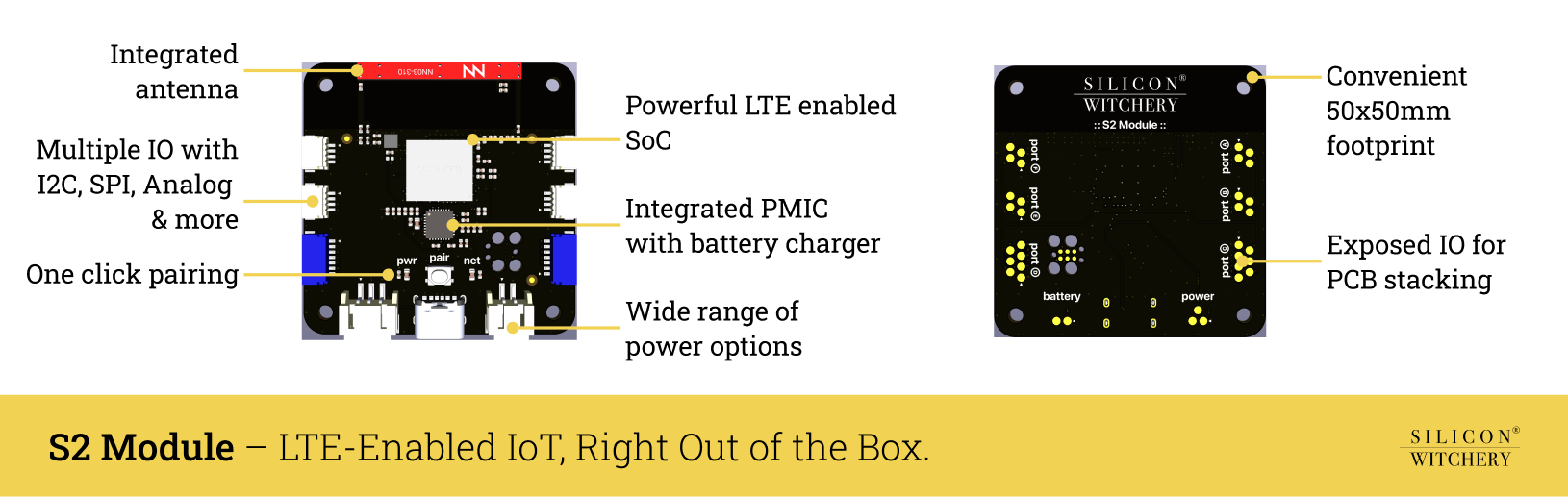
The S2 is a production-ready IoT module built around an advanced ARM SiP with integrated LTE Cat-M1 connectivity. Featuring comprehensive I/O support (SPI, I2C, analog), built-in GNSS, and sophisticated power management with battery charging capabilities. It’s designed for rapid deployment and remote development. The module comes pre-configured with a SoftSIM and flexible data plan, eliminating cellular integration complexity. Engineers can program and debug directly over LTE using our Lua-based runtime environment, with all device management and updates handled through the Superstack platform – no local toolchain required.
Feature summary
Hardware
- ARM SiP with integrated LTE Cat-M1 and GNSS
- Built-in antenna supporting major LTE bands
- Multiple I/O: SPI, I2C, analog inputs, GPIO
- Advanced power management with battery charging
- Multiple power inputs with low power modes
Connectivity
- Pre-configured softsim with global coverage
- No-contract data plan included
- One-click device pairing
- Variant with external antenna support available
Development
- Over-the-air programming and debugging
- Lua-based runtime environment
- Zero-touch firmware updates and fleet management
- No local toolchain required
Use cases
Industrial & Manufacturing
- Remote equipment monitoring and predictive maintenance
- Environmental monitoring in factories
- Production line automation and monitoring
Smart Agriculture
- Crop monitoring and automated irrigation
- Livestock tracking and health monitoring
- Weather station networks
Smart Cities & Infrastructure
- Energy consumption optimization
- Environmental sensing networks
- Waste management optimization
- Occupancy monitoring
- Traffic flow monitoring
Supply Chain & Logistics
- Cold chain monitoring
- Asset tracking and management
- Warehouse automation
- Fleet tracking and diagnostics
Contents
- Block diagram
- Pinout
- Status LEDs & button
- LTE & GNSS connectivity
- Power & battery interface
- Programming
- Schematic
- Characteristics
- Housing & mounting
- Labeling
- Mechanical dimensions
- Ordering information
- Compliance
- Terms of purchase
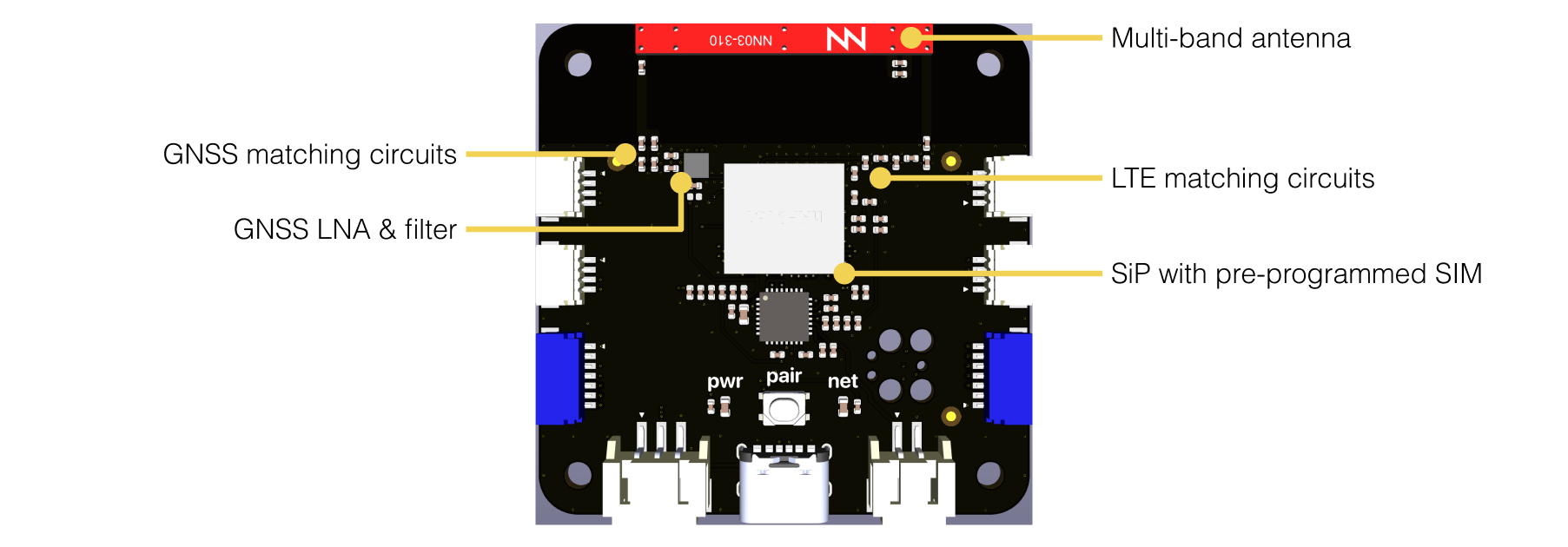
Block diagram
The S2 Module features two key devices:
- ARM Cortex-M33 System in Package with Cellular & GNSS - Nordic nRF9151
- Power management IC with switching regulation & battery charging - Nordic nPM1300
The module includes all supporting circuitry such that no external hardware except a simple power source is needed to operate the device.

The device exposes a range of I/O that can be used to connect external devices and features smart power management to run off either external power or a single-cell lithium polymer battery, saving power whenever possible.
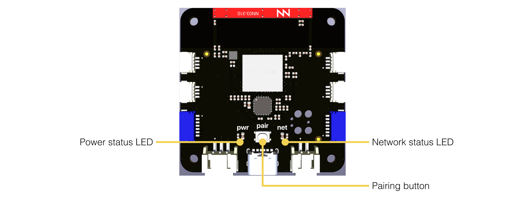
A single button is included for easy setup and two status LEDs indicate network and power status at a glance.
A multi-band antenna is included on the module supporting all the required LTE and GPS bands for global operation. A variant with external antenna connectors is available for designs where the built-in antenna is not suitable.
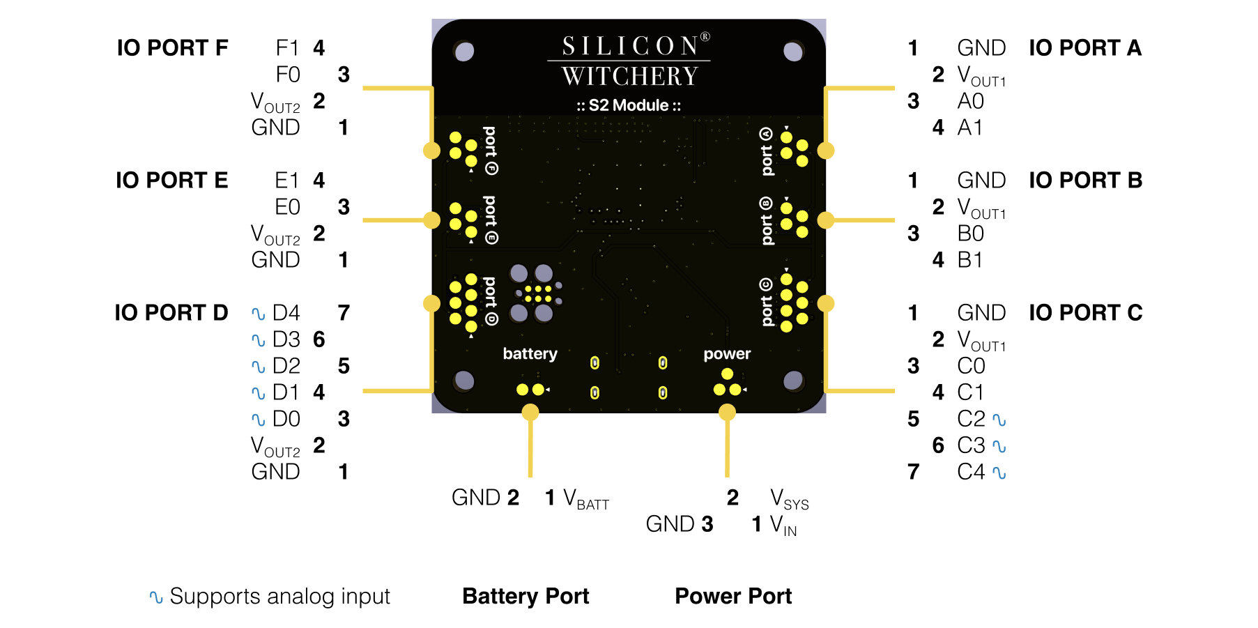
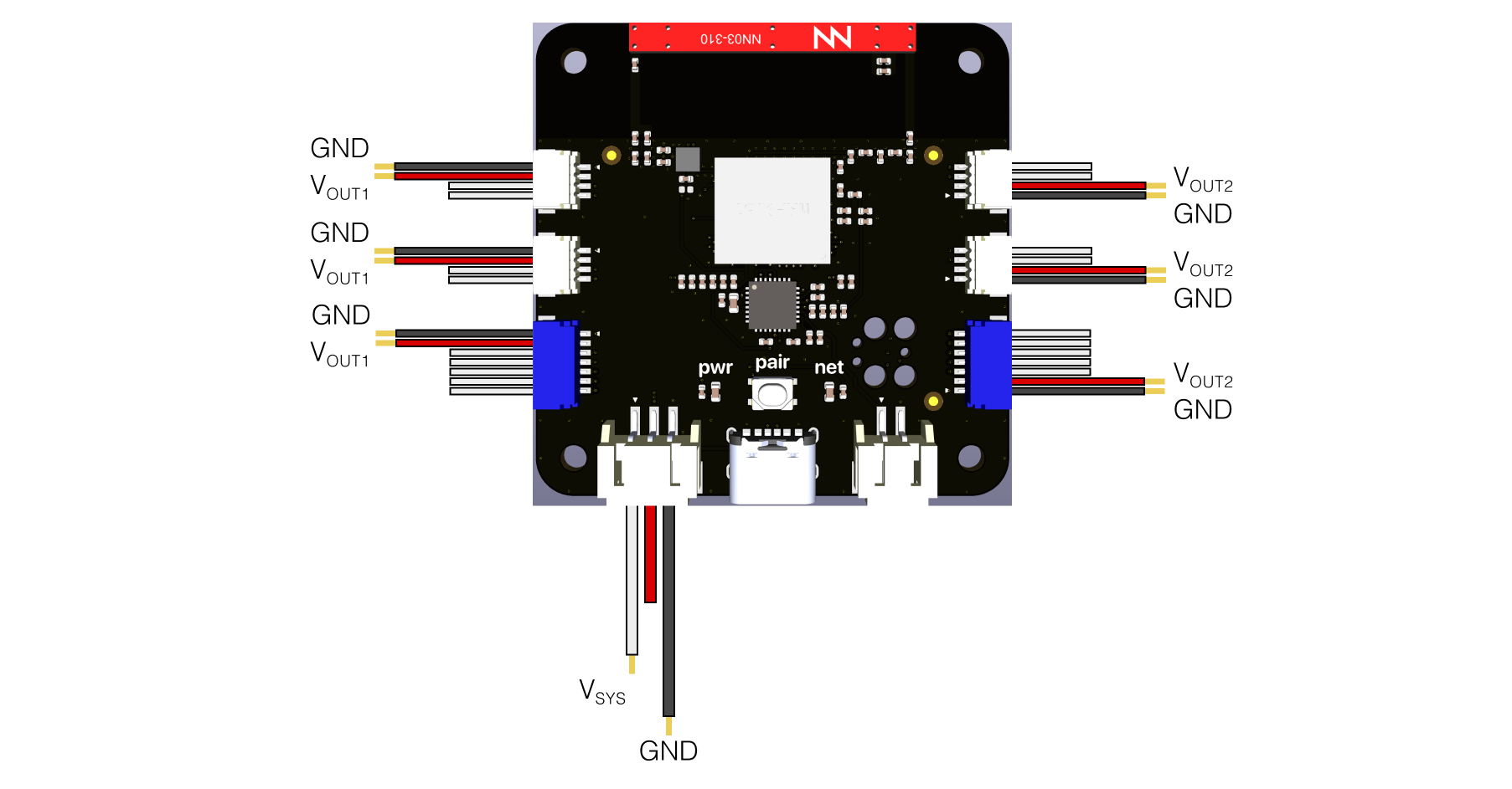
Pinout
The S2 Module features six IO ports and three power ports. Digital IO is freely configurable across all ports, while analog inputs are limited to certain pins. A detailed description of all the pins is shown in the diagram below.
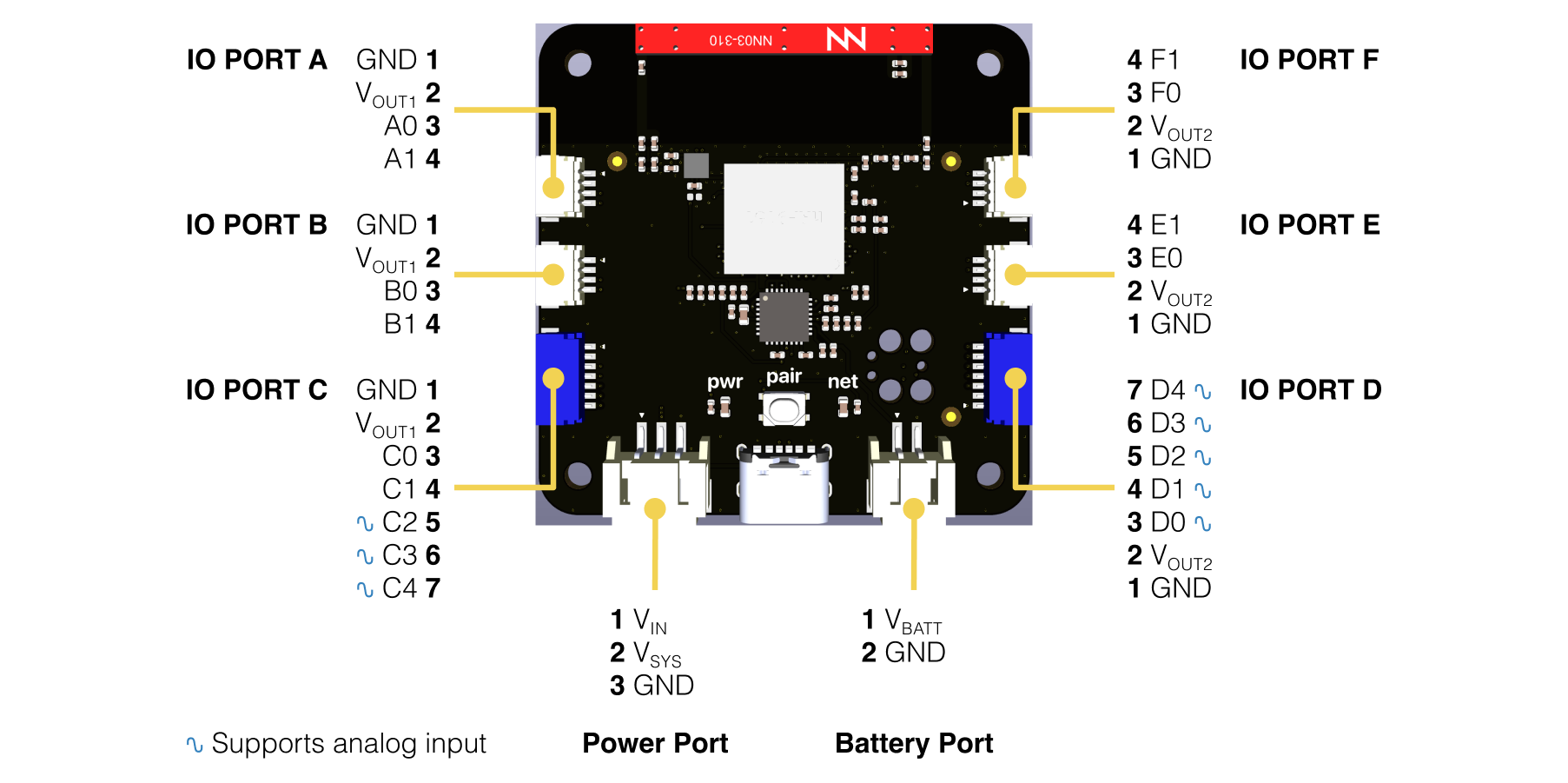
The bottom of the module additionally exposes the same IO as the physical connectors such that the board can be mounted to a carrier PCB and electrically interfaced via pogo-pins. See the section on mechanical dimensions for a recommended landing pattern.
Status LEDs & button
The on-board button is only used for initial pairing of the device with the cloud. Once paired, the button has no other functionality. This is to prevent tampering with the device when in the field. If needed, the device can later be unpaired from within Superstack and then paired again to a different deployment using the button.
The status LEDs, meanwhile, indicate the networking and power status of the device throughout the lifetime of the application.
The table below describes each of the LED states.
| Power LED | Meaning |
|---|---|
| Short blinks ▁▇▁▁▁▁▁▁▁▁▇▁▁▁ | Running on battery power – No external power detected |
| Slow blinking ▇▇▇▇▁▁▁▁▇▇▇▇▁▁ | Battery charging |
| Solid ▇▇▇▇▇▇▇▇▇▇▇▇▇▇ | Battery charged |
| Short blanks ▇▇▇▁▇▇▇▇▇▇▇▇▁▇ | Running on external power – No battery detected |
| Network LED | Meaning |
|---|---|
| Slow blinking ▇▇▇▇▁▁▁▁▇▇▇▇▁▁ | Searching for LTE network |
| Solid ▇▇▇▇▇▇▇▇▇▇▇▇▇▇ | Network found – Not connected to deployment |
| Fast blinking ▇▇▁▁▇▇▁▁▇▇▁▁▇▇ | Button pressed – Pairing to deployment |
| Off ▁▁▁▁▁▁▁▁▁▁▁▁▁▁ | Connected & idle |
| Short blinks ▁▇▁▁▁▁▁▁▁▁▇▁▁▁ | Data transmission |
| Strobe ▁▇▁▇▁▇▁▇▁▇▁▇▁▇ | Firmware updating Do not power off |
Automatic firmware updates
We periodically release firmware updates which enables connectivity between the S2 Module and Superstack. Updates are rolled out automatically and require no user intervention.
If you see a continuous strobe on the network led, this means that an update has begun. The process takes around 5 minutes, during which the module will reboot and may not show any LED activity during the final part of the update. It is important to not power off the device during this period as this will cause the update process to restart. Simply wait the full time until the device has rebooted and reconnects to the network.
LTE & GNSS connectivity
The S2 Module ships with LTE Cat-M1 enabled with support for the following bands: 1, 2, 3, 4, 5, 8, 18, 19, 20, 25, 26, 65, and 66. All of which are supported by the integrated antenna. Additionally, the external antenna variant of the module supports the following bands: 12, 13, 17, 28, and 85.
A softsim is pre-programmed into each module for included connectivity out of the box, where data allowance can be managed from inside the Superstack webapp.
The following regions are currently included in the data plan with more being regularly added.
| Region | Connected | Region | Connected soon |
|---|---|---|---|
| Austria | ✅ | Argentina | Validated |
| Belgium | ✅ | Australia | Validated |
| Colombia | 📶 | Brazil | Validated |
| Denmark | ✅ | Canada | Validated |
| Finland | ✅ | Chile | Validated |
| France | ✅ | China | Validated |
| Germany | ✅ | Costa Rica | Validated |
| Iceland | 📶 | Croatia | Validated |
| Japan | 📶 | Czechia | Validated |
| Latvia | ✅ | Ecuador | Validated |
| Luxembourg | 📶 | Estonia | Validated |
| Mexico | 📶 | Faroe Islands | Validated |
| Netherlands | ✅ | Greece | Validated |
| New Zealand | 📶 | Hong Kong | Validated |
| Norway | ✅ | Hungary | Validated |
| Romania | ✅ | India | Validated |
| Slovakia | ✅ | Ireland | Validated |
| Slovenia | ✅ | Israel | Validated |
| Spain | ✅ | Jamaica | Validated |
| Sweden | ✅ | Korea | Validated |
| Switzerland | 📶 | Liechtenstein | Validated |
| Taiwan | ✅ | Lithuania | Validated |
| United Kingdom | ✅ | Poland | Validated |
| United States | 📶 | Portugal | Validated |
| Uruguay | 📶 | Puerto Rico | Validated |
| Saudi Arabia | Validated | ||
| Singapore | Validated | ||
| Thailand | Validated | ||
| Turkey | Validated | ||
| United Arab Emirates | Validated |
📶 - External antenna variant of the module is recommended for this region
The module also supports GPS L1 C/A and QZSS L1 C/A reception with a maximum accuracy of 2.0m in continuous tracking mode, or 3.4m in periodic tracking mode.
Antenna considerations
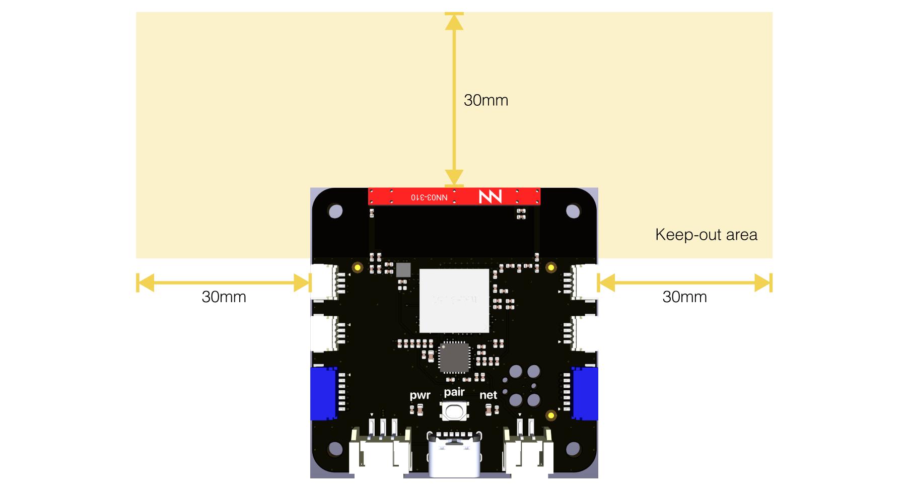
The S2 Module features an integrated multi-band antenna supporting all the LTE and GPS bands mentioned above. To ensure optimal performance of the antennas, the antenna area must be kept clear of metal objects, and the module must not be placed inside an enclosed metal area.
For optimum GPS accuracy, the antenna should have line of sight to open sky.
External antenna variant
If the mounting requirements for the module within an installation make it difficult for the integrated antenna to receive good reception, then a variant of the module is available with external antenna connectors. This variant allows the module to be placed inside metal enclosures with antenna routed outside to achieve better reception.
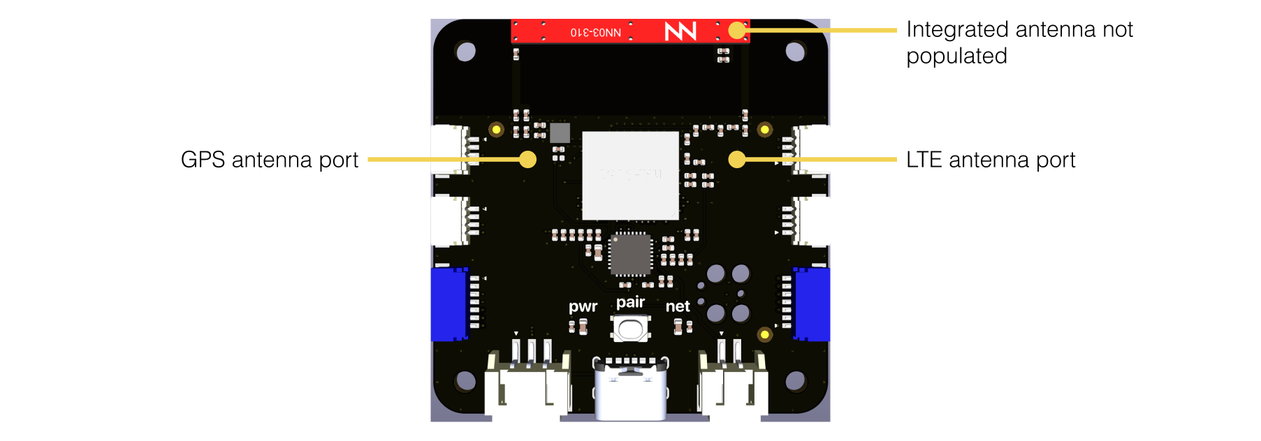
A wide variety of external antennas are available from various manufacturers. LTE antennas should support 698-960MHz and 1745-2200MHz with a VSWR of 3 or better. GPS antennas should support 1575MHz with a VSWR of 2 or better.
Examples of external antennas are listed below:
Power & battery interface
The S2 Module features an extensive power management solution built in. It can be powered in a variety of ways, includes lithium battery charging capabilities, as well as outputting multiple voltages to power sensors or other low power electronics. Additionally, the power management ensures low power operation of the module, saving power whenever possible.
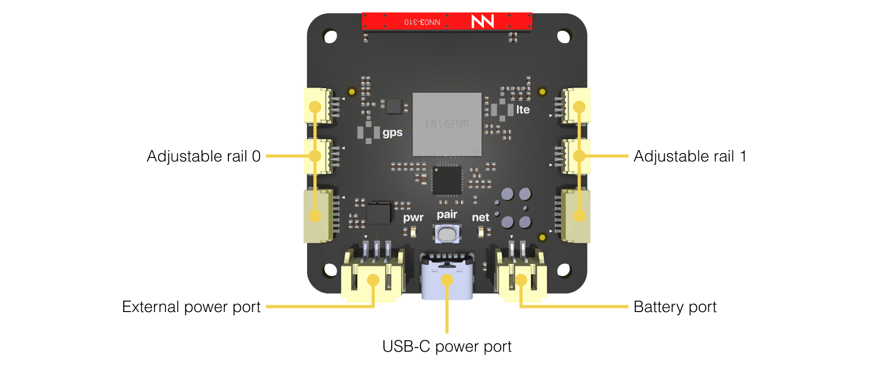
Power inputs
The S2 Module features three options for input power:
- Standard 5V USB-C input – VUSB
- External 5 - 17VDC input – VIN
- Single lithium polymer cell – VBATT
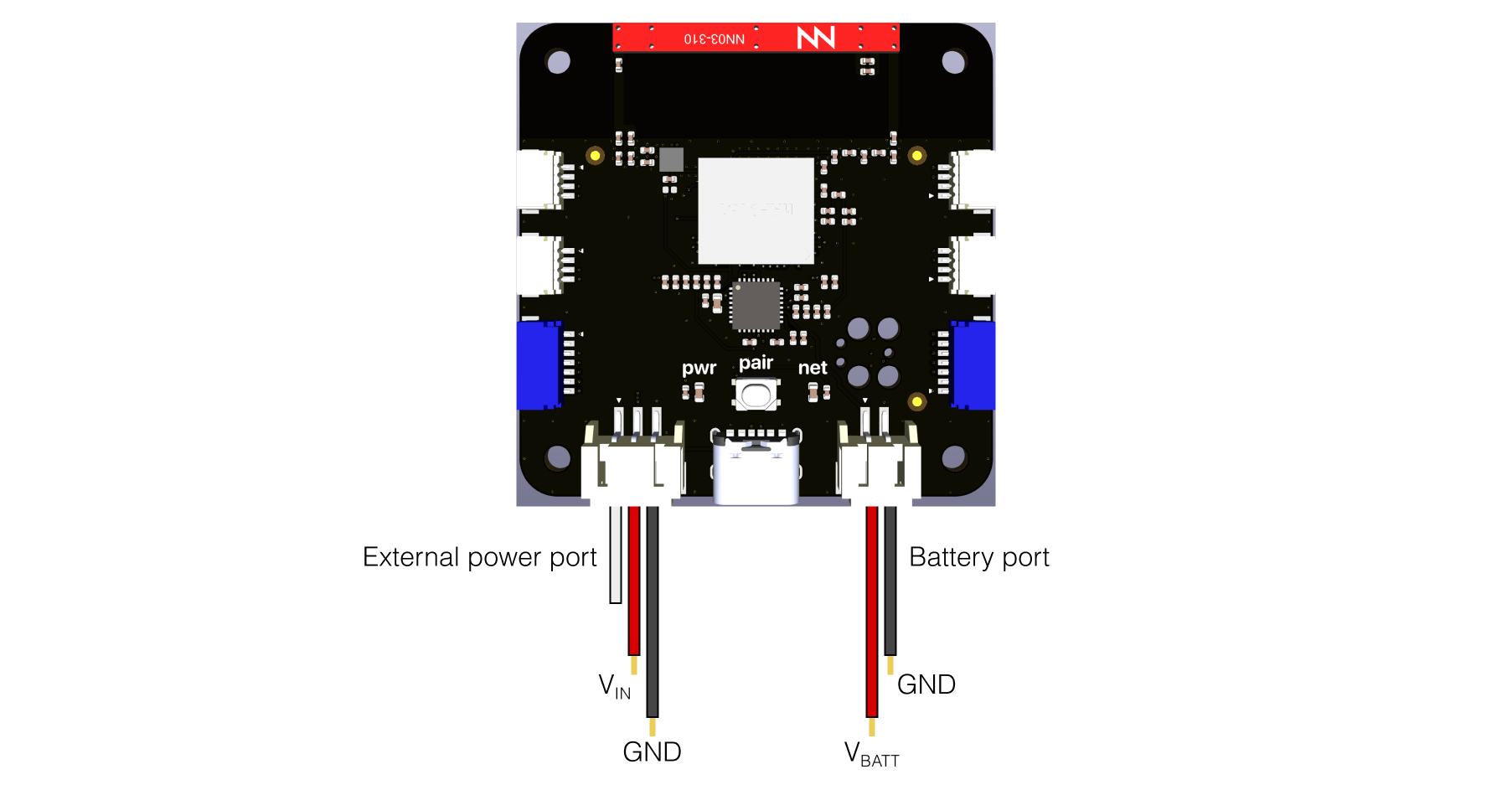
The USB-C input includes the proper negotiation with hosts to ensure the correct voltage and current is provided to the module. Voltage is always negotiated at 5V, with current draw either 500mA or 1A depending on the host capabilities.
The external power port allows powering of the module from a DC voltage between 5 and 17V. Up to 1A may be drawn.
Finally, power can also be provided via a single lithium polymer cell. Further details on cell specifications are shown in the battery charging section below, as well as the electrical characteristic tables.
Power outputs
The module has two voltage outputs which can be used for powering external sensors or components. VOUT1 and VOUT2 are adjustable, while VSYS is fixed.
| Rail | Exposed on | Max current draw | Adjustable voltage output |
|---|---|---|---|
| VOUT1 | PORTA, PORTB, PORTC | 100mA across all ports | Off or 1.8 - 3.3V * |
| VOUT2 | PORTD, PORTE, PORTF | 100mA across all ports | Off or 1.8 - 3.3V * |
| VSYS | External Power Port | 1A ⁑ | 5V |
* – The voltage on **VOUT1** and **VOUT2** are derived from the same internal source, therefore always track the same voltage. They can however be independently turned off to selectively shut down sensors that aren't in use.
⁑ – VSYS is a 5V regulated output which powers everything on the module including VOUT1, VOUT2, the radio and battery charging. Its current capability is therefore highly dependent on what else is being powered. Assuming a suitable power input to one of the input ports, VSYS is capable of providing up to 1A of current.
Battery charger
The module features charging from a single lithium cell at a configurable current from 32mA to 800mA. The charge termination voltage can also be configured from 3.5V to 4.45V. Higher capacity cells may be used, but will result in slower charge times.
The module features thermal regulation such that if the ambient temperature is too high to safely charge the battery, the PMIC will throttle the charge current to prevent damaging the cell. To ensure this feature works as expected, the cell must be placed against the module, and the designer should ensure to minimize any temperature differential between the cell and the module.
Programming
The S2 Module comes pre-programmed with the Superstack firmware, server license, as well as a provided soft SIM with attached data plan.
It is not expected that the user should program the device directly, but rather use Superstack to run scripts on the device via the Superstack webapp.
If desired however, the module can be completely erased and a fully custom firmware may be loaded onto it. Note that this will also erase the SIM, data plan and superstack server license. After which it will be no longer possible to use the module with Superstack.
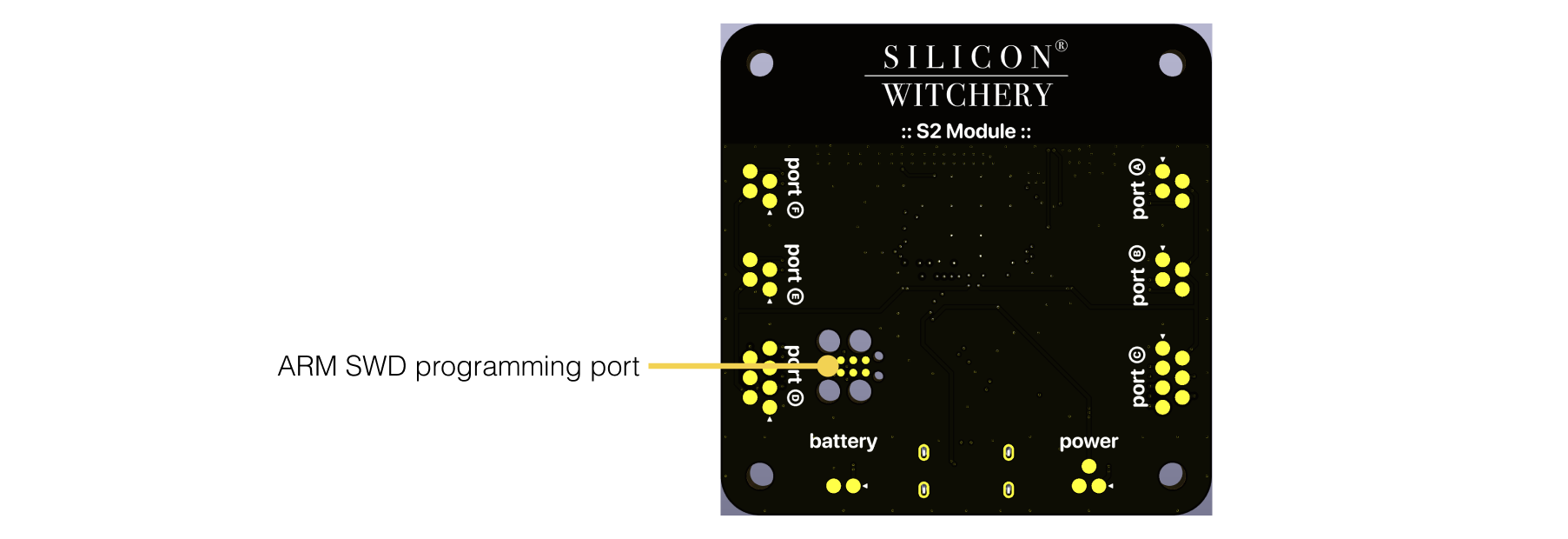
The S2 Module is compatible with Tag-Connect TC2030-CTX programming cables, which can be used in conjunction with Segger J-Link debug probes for firmware development and debugging.
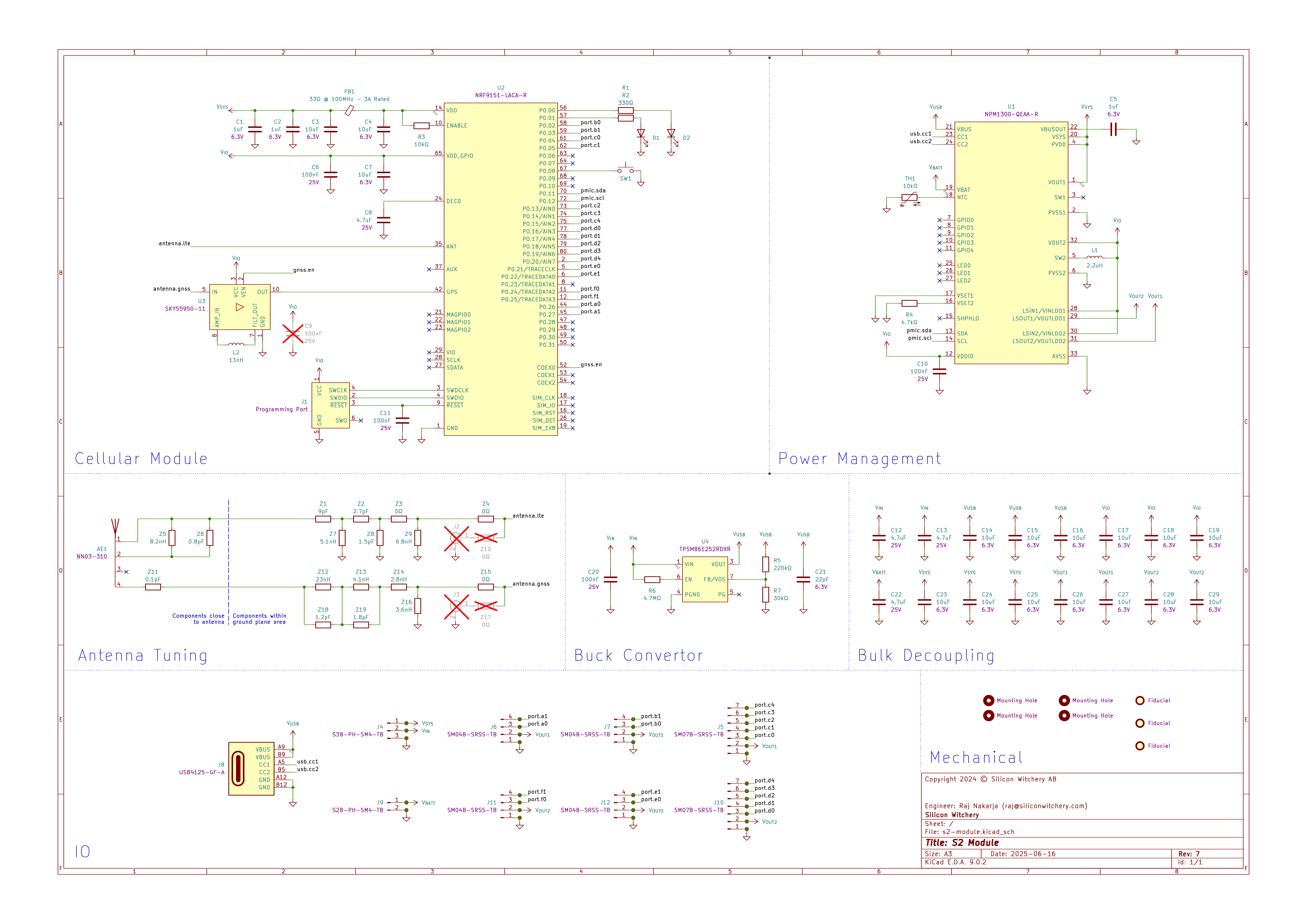
Schematic
The full schematic of the S2 Module is shown in the diagram below.
Characteristics
Ratings and characteristics of the module are listed below. For further details, the datasheets of the internal components may be referenced according to the schematic.
Absolute maximum ratings
| Description | Min | Max |
|---|---|---|
| USB input voltage: VUSB | -0.3V | 22V |
| External input voltage: VIN | -0.3V | 19V |
| Battery input voltage: VBATT | -0.3V | 5.5V |
| Output rail voltages: VSYS, VOUT1, VOUT2 | -0.3V | 5.5V |
| PORTA - PORTF IO voltages: | -0.3V | VOUTx + 0.3V |
| LTE port RF input level* | - | 10dBm |
| LTE port maximum mismatch from 50Ω* | - | VSWR of 10:1 |
| GPS port RF input level* | - | 10dBm |
| Storage temperature | -40°C | 95°C |
- – External antenna variant only
Recommended operating conditions
| Description | Min | Max |
|---|---|---|
| USB input voltage: VUSB | 4V | 5.5V |
| External input voltage: VIN | 5V | 17V |
| Battery input voltage: VBATT | 2.3V | 4.45V |
| Operating temperature | -40°C | 85°C |
Electrical characteristics
| Description | Min | Typ | Max |
|---|---|---|---|
| USB overvoltage protection threshold | - | 5.5V | - |
| USB power-on reset release voltage | - | 3.9V | - |
| USB brown-out trigger voltage with VBATT not present | - | 3.8V | - |
| USB brown-out trigger voltage with VBATT present | - | 3.6V | - |
| USB input current draw: IUSB | 1.8mA | - | 1A |
| Resistance between VUSB and VSYS | - | 300mΩ | - |
| External input current draw: IIN | 1mA | - | 1A |
| Battery power-on reset release voltage | - | 2.75V | - |
| Battery brown-out trigger voltage | - | 2.4V | - |
| Minimum VBATT voltage for charging | - | 2.1V | - |
| Range of battery charging termination voltage | 3.5V 4V | 50mA steps | 4V 4.5V |
| Range of battery charging constant current | 32mA | 2mA steps | 800mA |
| Range of battery discharge current limit | 290mA | - | 1A |
| Resistance between VBATT and VSYS | - | 160mΩ | - |
| Battery charger temperature accuracy | - | 2°C | - |
| Trickle charge timeout | - | 10min | - |
| Charging timeout in CC or CV mode | - | 7h | - |
RF characteristics
| Description | Min | Typ | Max |
|---|---|---|---|
| Supported LTE standard | - | LTE Rel-14 Cat-M1 HD-FDD | - |
| Supported LTE bands | - | B1, B2, B3, B4, B5, B8*, B12, B13, B18, B19, B20, B25, B26, B28, B66, B85 | - |
| LTE transmission bandwidth | - | 1.4MHz | - |
| LTE RX frequency range | 728MHz | - | 2200MHz |
| LTE RX sensitivity low band | -103dBm | -108dBm | - |
| LTE RX sensitivity high band | -103dBm | -107dBm | - |
| LTE TX frequency range | 698MHz | - | 1980MHz |
| LTE TX power output | -40dBm | - | Power class 3: 23dBm Power class 5: 20dBm |
| LTE port impedance⁑ | - | 50Ω | - |
| GPS sensitivity | TBD | - | TBD |
| GPS time to first fix | 1.3s | - | 30.5s |
| GPS accuracy | 1.8m | - | 3.1m |
| GPS port impedance⁑ | - | 50Ω | - |
* – Band 8 is only supported with the external antenna variant of the module
⁑ – External antenna variant only
Housing & mounting
Both variants of the module ships with a plastic housing, as well as a set of nylon screws and standoffs for easy mounting.
- 1x plastic housing
- 4x 12mm M2.5 countersunk screws
- 4x 6mm M2.5 hex standoffs
- 4x 4mm M2.5 pan head screws
The module may be mounted to either a chassis, or a host PCB. If using the internal antenna variant of the module, ensure that there are no metal objects close to the antenna.
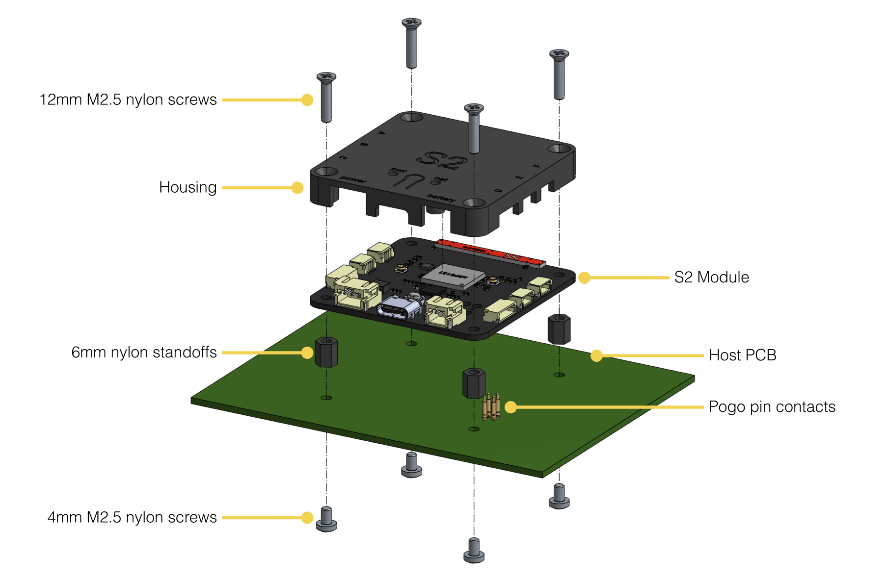
If mounted to a PCB, it is possible to interface with all of the module power and IO connections using spring loaded pogo pins which press against the gold pads on the bottom of the module. If using the included 6mm standoffs, the following pogo pins are suitable:
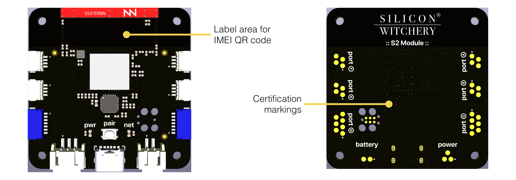
Labeling
The position of the pre-attached IMEI label is shown below. The label displays the IMEI in both text and QR code format as shown:
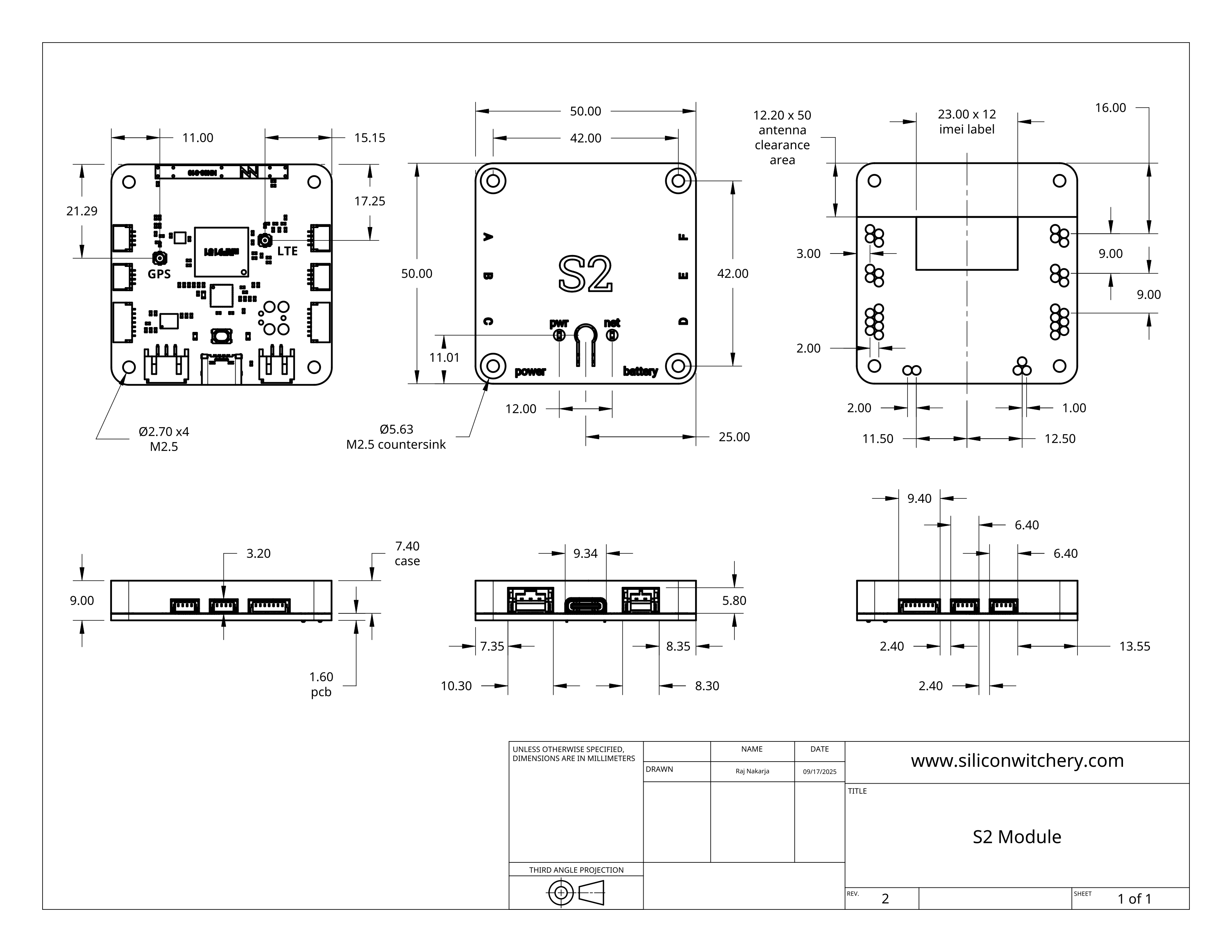
Mechanical dimensions
Dimensional drawings of the module are shown below.
Ordering information
The S2 Module is available in the following SKUs:
| Description | Part number | Package quantity |
|---|---|---|
| S2 Module with integrated antenna | S2-MODULE | 1 |
| S2 Module with external antenna connectors | S2-MODULE-EXT | 1 |
Compliance
Approved bands
Approved bands for the nRF9151 SiP are listed within Nordic’s documentation
Terms of purchase
The S2 Module and related software or hardware have not been approved for life-sustaining or other applications where failure may cause harm to human life, health, or damage to property or equipment. Additionally, they have not been designed according to any critical standards in order to guarantee performance or accuracy. No responsibility is assumed by Silicon Witchery for its use, nor for any infringements of patents or other rights of third parties that may result from its use. These specifications are subject to change without notice.
No liability is held by Silicon Witchery for any delay or failure in performance arising as a result of any occurrence beyond its reasonable control, including but not limited to, capacity constraints, accident, act of God, labor disputes, civil commotion, war, medical outbreak, unanticipated manufacturing problems, shortage of energy, raw materials or other supplies, requirements or acts of any government or agency thereof, including trade embargoes or medical quarantines, judicial action and/or failure or delays in transportation.
Purchasing parties agree to take responsibility that any delivered hardware, software, documentation and/or other materials, tangible or otherwise, shall not be consigned, transferred, re-exported or sold to any party or person in any way that does not adhere to the most current Export Control Regulations (“Regulations”) of the European Union Dual Use Regulations, and the Export Administration Regulations of the United States of America.
Silicon Witchery may hold back from delivering goods, services, or any other materials in its position, if it suspects they may be used outside the accordance of these Regulations.
The Purchasing Parties agree to indemnify and hold harmless Silicon Witchery against any damages, costs, losses, and/or liabilities arising out of any non-compliance with Regulations.